Orientation Marks, Reference Marks, and Layout – Part 1
Last week I posted a video that I made about 10-12 years ago on using layout tools properly. After watching the video, Bill Anderson* sent me an email with some very good comments that provide a lot more perspective on the reference marks that are typically used. Unfortunately, Bill tried to post his email as a comment and it wouldn’t go through for some reason, but the information that he provided is very useful and relevant so I decided to make a separate post out of it. I’m not going to post his email verbatim, rather I’m going to organize his thoughts along with mine into today’s post.
First, we should clearly distinguish that there is a difference between reference marks (used to identify a flat, straight, and square face, edge and corner) and orientation marks (used to identify the orientation of parts in an assembly). If you’re a veteran woodworker, you’re probably thinking “duh, obviously”. But for anyone that is relatively new to hand work, this is an important distinction to make, because the two different marks are really not interchangeable. Alone, neither set of marks provides the complete picture. However, together, they tell us not only the orientation of the various parts, but also where the joinery goes and how it should be laid out.

The simplest of the two are the orientation marks, and these are useful regardless of whether you do most of your work by hand or by machine. The purpose of orientation marks is to tell you where the parts go in the overall assembly. Orientation marks are typically made on the face, edge, or end where they will provide the most useful information with the fewest number of marks – typically the one that faces up. Of course you can use whatever kind of orientation marks you want, and that make sense to you. Nobody is going to put you in woodworker jail for using the wrong orientation marks. However, the most traditional, an in my opinion, the most useful, is the carpenter’s/cabinetmaker’s triangle.
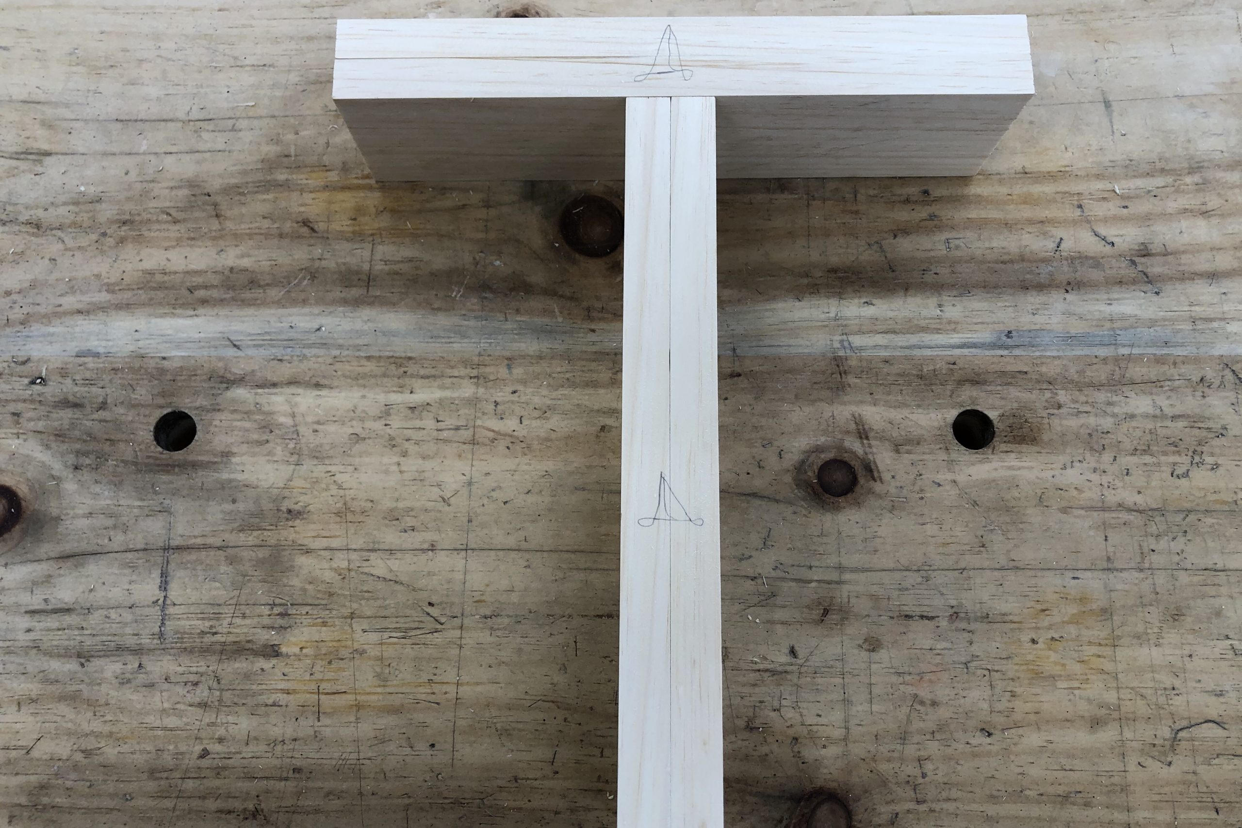
I think the best way to understand the use of the cabinetmaker’s triangle is to see it in use with some actual project parts. So let’s take a few examples. The first is a panel glue-up. Pictured above are four boards that I have arranged how I would like them to be in the panel after glue-up. If these boards get separated (and they will), the triangle will tell me which face is up, which end is the left and which is the right, and in what order the boards need to be arranged from top to bottom. The number in the corner tells me that these four boards are all for panel #3 (I’m gluing up multiple, similarly sized panels).

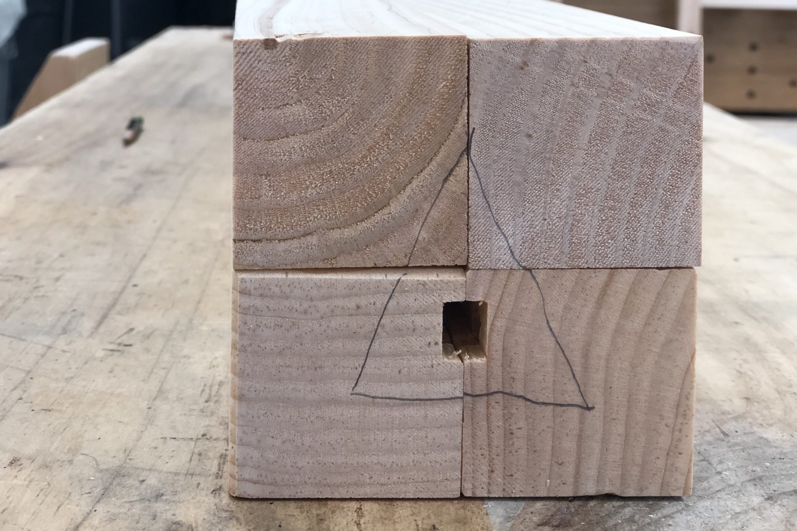
The next example is useful for a set of four table legs (or in this case, the four legs of a head board and foot board for a bed). In this case, marking the faces wouldn’t be as helpful because the boards are arranged in a square rather than a flat arrangement. Therefore, rather than putting the orientation marks on the face of the boards, I put it on the end grain. By marking the orientation on the end grain, I can very quickly orient the legs not just into their proper corner, but also, I can rotate them around their long axis to ensure that I have the appropriate face and edge facing out.

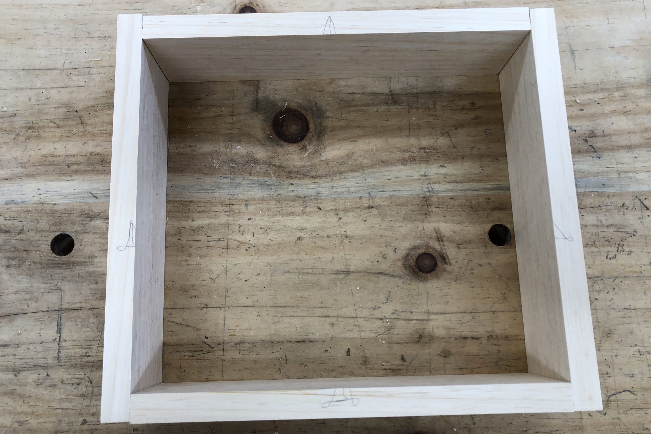
The last example of using orientation marks is for a drawer (but could also apply to other, similar situations, such as the four aprons of a table). In this case, I use two sets of marks – one set for the sides, and one set for the front/back. I also make the marks on the edges of the parts in this example as marking the faces or ends would be less useful and require many more marks. Notice also that I’m using a slightly fancier version of the triangle here, sometimes referred to as the French cabinetmaker’s triangle, because it is most recognizable from Roubo’s tome on the craft. This version of the triangle helps to distinguish it from the reference mark known as a “carat”, used to denote a flat, straight, and square edge (I’ll talk about these marks later).

In the case of the drawer, the two marks tell me everything I need to know about the parts. I can look at them and immediately know which side the part goes on, where the front is and where back is, where the inside and outside faces are, and where the top and bottom of the drawer are. Similarly to the glued-up panel example above, if I’m making multiple drawers, I’ll add a number or letter to the triangle to indicate which drawer the parts belong to.
So as you can see, using orientation marks is extremely important in furniture making, and, in my opinion, the triangle is the simplest, most efficient, and least confusing type of orientation mark to use. You may disagree, and that’s fine, but you should definitely employ some kind of orientation marking system in your work, and be consistent about the system that you use and how you use it. Doing so will help you to make fewer preventable mistakes in your work, and save you lots of frustration.
So with orientation marks thoroughly covered, the next marking system to cover will be the reference marks. However, as this post has gotten quite long already, I’ll cover the reference marks in Part 2.
* If you are not familiar with Bill’s work, I strongly urge you to check it out. He has done professionally produced videos with Wood & Shop and Popular Woodworking, written for Popular Woodworking Magazine, appeared multiple times as a guest on The Woodwright’s Shop and is a regular instructor at The Woodwright’s School (what a dream gig!). He also builds custom furniture and sells parts for his reproduction of the Howarth bowsaw on his website Edwards Mountain Woodworks.
Tag:Layout
